1. Introduction
CDMA mobile network authentication mechanism evolved with the network evolution from CDMAone to CDMA2000 Rev.0, A, B, C and later.
Cellular Authentication and Voice Encryption (CAVE) is the mechanism used in CDMA2000 Rev.B and earlier generations. Authentication and Key Agreement (AKA) plus optional UIM authentication procedure to prove presence of a valid UIM and prevent rogue shell attacks is an enhanced mechanism used by CDMA2000 Rev C and later generations. With the network gradually migrates toward all IP solutions, IS-856 specified the authentication and security key assignment mechanism used for authenticating mobile users with RAN/PDSN etc. core network elements.
2. CAVE
CAVE is the access authentication mechanism used in CDMA/1xRTT Rev.B and earlier systems. Two key network entities involved in the CAVE-based authentication are the Authentication Center (AC) a.k.a. HLR/AC, AuC, and the Visitor Location Register (VLR).
Authentication Center (AC) is a home network element, responsible for controlling the authentication process by either authenticating the Mobile Station or sharing the shared secret data (SSD) with the serving VLR to allow authentication bing done locally.
Visitor Location Register (VLR) is in the visiting network. If SSD is shared with the visited network, the VLR can locally authenticates a roamer. Otherwise, the VLR proxies authentication requests and responses between the roamers and their home HLR/AC for authentication.
CAVE uses a symmetry key cryptosystem together with a Challenge-Response protocol to achieve the authentication functions. It is based on the CAVE algorithm and two shared keys, respectively the Authentication key (A-key) – A 64-bit primary secret key known only to the MS and AC, and the Shared Secret Data (SSD) – A 128-bit secondary secret key that is calculated using the CAVE algorithm during an SSD Update procedure. SSD consists of two 64-bit keys: SSD_A, which is used during authentication to calculate authentication signatures, and SSD_B, which is used in the generation of session keys for encryption and voice privacy.
CAVE-based authentication provides two types of challenges, Global challenge and Unique challenge respectively.
Global challenge is the procedure that requires any MS attempting to access the serving network to respond to a common challenge value being broadcast in the overhead message train. The MS must generate an authentication signature response (AUTHR) using CAVE with inputs of the global challenge value, ESN, either the last six dialed digits (for an origination attempt) or IMSI_S1 (for any other system access attempt), and SSD_A.
AUTHU generation for global challenge

Global challenge when SSD is not shared

Global challenge when SSD is shared

Unique challenge is the procedure that allows a visited network (if SSD is shared) and/or home network to uniquely challenge a particular MS for any reason. The MS must generate an authentication signature response (AUTHU) using CAVE with inputs of the unique challenge value, ESN, IMSI_S1, and SSD_A.
AUTHU generation for unique challenge

Unique challenge initiated by roamer’s home system

Unique challenge initiated by visited system

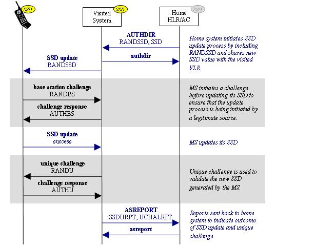
SSD update process when SSD is not shared

SSD update process when SSD is shared

3. AKA
AKA stands for the Authentication and Key Agreement. It is a security protocol used in 3G networks (both CDMA and UMTS). In the CDMA world, it is the successor to the CAVE-based Authentication. AKA provides procedures for mutual authentication of the MS and serving system. The successful execution of AKA results in the establishment of a security association (i.e., set of security data) between the MS and serving system.
Compared to the CAVE-based authentication, AKA has the following advantages
--> Larger authentication keys (128-bit )
--> Stronger hash function (SHA-1)
--> Support for mutual authentication
--> Support for signaling message data integrity
--> Support for signaling information encryption
--> Support for user data encryption
--> Protection from rogue MS when dealing with R-UIM
In order to ensure interoperability with current devices and partner networks, support for AKA in CDMA networks and handsets will likely be in addition to CAVE-based authentication.
.JPG)
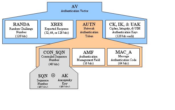
Authentication vectors (AVs)
A fundamental concept in AKA is the authentication vector (AV). An AV is essentially a group of information used for one AKA attempt. AVs are generated by the home AC and distributed to the visited network. Each AV contains all information required by the visited network to locally perform AKA with an AKA-enabled mobile station.

AKA authentication process
Similar to CAVE, AKA relies on an authentication key associated with the MS and available only to the MS and its home AC. In CAVE, this key is known as the authentication key (A-key). In AKA, the key is known as the master key (K).
Also similar to CAVE, AKA involves a challenge process that allows the network to authenticate the MS. However, in AKA the information provided during this challenge also enables the MS to authenticate the network, providing for bilateral authentication.
An AKA process includes 4 phases
1. Distribution of AVs. Authentication vectors (AVs) are generated by the home system and provided to the visited system in an AV list
2. Authentication of the network by the MS. The message authentication code (MAC_A) received from the network is verified against the expected MAC_A (XMAC_A) generated by the MS. The sequence number (SQN) received from the network is verified against the SQN locally maintained by the MS.
3. Authentication of the MS by the network. The authentication response (RES) received from the MS is verified against the expected RES (XRES) received from the home system in the network authentication token (AUTN).
4. Establishment of security association between MS and MSC. Cipher key (CK), integrity key (IK), and UIM authentication key (UAK) are generated by the MS in such a way that they are identical to the ones provided to the visited network in the AV. The security association between MS and MSC involves using these keys to support security services such as confidentiality and integrity.

4. IS-856 Authentication
In IS-856 Authentication mechanism, RAN and PDSN are the two network elements that serve authenticating the mobile users.
* RAN:
--> Initial connection establishment is neither authenticated nor encrypted.
--> Session establishment includes Diffie-Hellman key negotiation.
--> Subsequent RAN-domain messages can be authenticated and/or encrypted using the negotiated keys.
--> PPP/LCP setup follows session establishment.
--> RAN user identity is optionally authenticated by CHAP via the RAN-AAA.
--> Data integrity protection (encryption, keyed MAC) prevents packet insertion or similar theft of service.
* PDSN:
--> Separate PPP/LCP instance created.
--> CHAP and/or MIP authentication of PDSN user identity via the home AAA server.
--> RAN security ensures integrity of the PPP connection.


")
")
")
")
")
")
")
")
")
")
")
")
")
")


.JPG)