Search This Blog

Friday, August 6, 2010

3GPP UMTS Authentication and Key Agreement

1. Overview

3GPP defined authentication and key agreement procedure specified in TS 33.102 V9.2.0 (2010-03) defined the mechanism for achieving mutual authentication between the user and the network by showing knowledge of a secret key K which is shared between and available only to the Universal Subscriber Identity Module (USIM) and the AuC in the user's Home Environment (HE).

The mechanism was chosen to achieve maximum compatibility with the current GSM security architecture and facilitate migration from GSM to UMTS.

The mechanism is composed of a challenge/response protocol identical to the GSM subscriber authentication and key establishment protocol combined with a sequence number-based one-pass protocol for network authentication derived from ISO/IEC 9798-4(section 5.1.1).


2. Authentication Vector Distribution

Upon receipt of a request from the VLR/SGSN, the HE/AuC sends an ordered array of n authentication vectors (the equivalent of a GSM "triplet") to the VLR/SGSN. The authentication vectors are ordered based on sequence number.

Each authentication vector consists of the following components:
--> a random number RAND,
--> an expected response XRES,
--> a cipher key CK,
--> an integrity key IK and
--> an authentication token AUTN.

Each authentication vector is good for one authentication and key agreement between the VLR/SGSN and the USIM.

3. Authentication and key Establishment

When the VLR/SGSN initiates an authentication and key agreement with the MS, it selects the next authentication vector from the ordered array and sends the parameters RAND and AUTN to the MS.

The MS/USIM checks whether AUTN can be accepted and, if so, produces a response RES which is sent back to the VLR/SGSN. The MS/USIM also computes CK and IK.

The VLR/SGSN compares the received RES with XRES. If they match the VLR/SGSN considers the authentication and key agreement exchange to be successfully completed.

The established keys CK and IK will then be transferred by the MS/USIM and the VLR/SGSN to the entities which perform ciphering and integrity functions.

4. Other Aspects

VLR/SGSNs can offer secure service even when HE/AuC links are unavailable by allowing them to use previously derived cipher and integrity keys for a user so that a secure connection can still be set up without the need for an authentication and key agreement. Authentication is in that case based on a shared integrity key, by means of data integrity protection of signalling messages.

5. Authentication Vector (AV) Generation

Authentication vector (AV) is generated by the HE/AuC.


f1 and f2 are message authentication functions, f3, f4 and f5 are key generating functions.

6. User Authentication Function

Upon receipt of RAND and AUTN the USIM first computes the anonymity key AK = f5K (RAND) and retrieves the sequence number SQN = (SQN * AK) * AK.

After that, the USIM computes XMAC = f1K (SQN || RAND || AMF) and compares this with MAC which is included in AUTN. If they are different, the user sends user authentication reject back to the VLR/SGSN with an indication of the cause and the user abandons the procedure. In this case, VLR/SGSN shall initiate an Authentication Failure Report procedure towards the HLR. VLR/SGSN may also decide to initiate a new identification and authentication procedure towards the user.

Finally, the USIM verifies that the received sequence number SQN is in the correct range. If the USIM considers the sequence number to be not in the correct range, it sends synchronisation failure back to the VLR/SGSN including an appropriate parameter, and abandons the procedure.

Tuesday, August 3, 2010

Mobile Network Numbering and Routing

1. Overview

* Mobile Subscriber ISDN Number (MSISDN)
--> is a number uniquely identifying a subscription in a mobile network.
--> it is the telephone number of the SIM card in a mobile/cellular phone.
--> it is Mapped to the Mobile Station Roaming Number (MSRN) by HLR.

* International Mobile Subscriber Identify (IMSI)
--> is a unique number associated with all mobile phone users.
--> Stored in SIM/HLR

* Temporary Mobile Subscriber Identity (TMSI)
--> is randomly assigned by the VLR to every mobile in the area, the moment it is switched on.
--> is local to a location area
--> is assigned by VLR and stored in VLR

* International Mobile Equipment Identity (IMEI)
--> Unique ID to handset, used by air interface

2. Encoding

* MSISDN = CC + NDC + SN
--> MSISDN: Mobile Station ISDN Number
--> CC: Country Code
--> NDC: National Destination Code
--> SN: Subscriber Number

* IMSI = MCC + MNC + MSIN
--> IMSI: International Mobile Subscriber Identity
--> MCC: Mobile Country Code
--> MNC: Mobile Network Code
--> MSIN: Mobile Station Identification Number

* MSRN = CC + NDC + SN
--> MSRN: Mobile Station Roaming Number
--> CC: Country Code
--> NDC: National Destination Code
--> SN: Subscriber Number

* LAI = MCC + MNC + LAC
--> MCC: Mobile Country Code
--> MNC: Mobile Network Code
--> LAC: Location Area Code

* IMEI = TAC + FAC + SNR + spare
--> IMEI: Internal Mobile Equipment Identity
--> TAC: Type Approval Code
--> FAC: Final Assembly Code
--> SNR: Serial Number

* IMEISV = TAC + FAC + SNR + SVN
--> IMEISV: International Mobile Equipment Identity and Software Version Number
--> SVN: Software Version Number

* CGI = MCC + MNC + LAC + CI
--> CGI: Cell Global Identity
--> CI: Cell Identity
--> BSIC: = NCC + BCC
--> BSIC: Base Station Identity Code
--> NCC: Network Color Code (3bits)
--> BCC: Base Station Color Code (3bits)

* LN = CC + NCD + LSP
--> LN: Location Number
--> CC: Country Code
--> NCD: National Destination Code
--> LSP: Locally Significant Part

* RSZI = CC + NDC + ZC
--> RSZI: Regional Subscription Zone Identity
--> CC: Country Code
--> NDC: National Destination Code
--> ZC: length of the Zone code (2 octets)

3. Usage

* Information resident in MS & SIM
--> IMSI
--> TMSI
--> IMEI
--> misc. information

* Routing Information used by Network
--> MSISDN
--> MSRN

4. Numbering and Routing


Wednesday, July 28, 2010

Mobile Network Evolution: UMTS


Universal Mobile Telecommunications System (UMTS) is one of the third-generation (3G) cell phone technologies. Currently, the most common form of UMTS uses W-CDMA as the underlying air interface. It is standardized by the 3GPP, and is the European answer to the ITU IMT-2000 requirements for 3G cellular radio systems.

UMTS is packet-based and it allows transmission of text, digitized voice, video, and multimedia at data rates up to 2 megabits per second (Mbps). UMTS offers a consistent set of services to mobile computer and phone users, no matter where they are located in the world.

1. UMTS Network Architecture

A UMTS network consists of three domains; Core Network (CN), UMTS Terrestrial Radio Access Network (UTRAN) and User Equipment (UE). The main function of the core network is to provide switching, routing and transit for user traffic. Core network also contains the databases and network management functions.

The basic Core Network architecture for UMTS is based on GSM network with GPRS. All equipment has to be modified for UMTS operation and services. The UTRAN provides the air interface access method for User Equipment. Base Station is referred as Node-B and control equipment for Node-B's is called Radio Network Controller (RNC).


2. UMTS Protocol Stacks

Friday, July 16, 2010

Mobile Network Evolution: EDGE


EDGE, Enhanced Data rates for GSM Evolution, is a further step for GSM to migrate to 3G. It uses a new air-interface technology -- 8 Phase Shift Keying Modulation (8-PSK) to offer 48 kbits/s per GSM timeslot. The overall offered data speeds of 384Kbps places EDGE as an early pre-taste of 3G and it is actually labeled as 2.75G by the industry.

EDGE is occasionally referred to as Enhanced GPRS (EGPRS) because it increases the capacity and data throughput of GPRS by three to four times. Like GPRS, EDGE is a packet-based service, which provides customers with a constant data connection.

1. EDGE Network Architecture
On top of the GPRS network, it is only necessary to upgrade the MS and the radio access network RAN (BTS + BSC) to support the EDGE functionalities. The RAN for EDGE is referred as GERAN (GSM/EDGE Radio Access Network).


2. EDGE Network Entities

All EDGE network entities are same as those of GPRS except that the MS and the BTS are upgraded with new physical layers to support the new modulation technology. Some industrial notations also included the migration of BSC to RNC (Radio Node Controller) into the EDGE for the new Iu-cs and Iu-ps interface support.


3. EDGE Interfaces and Protocols

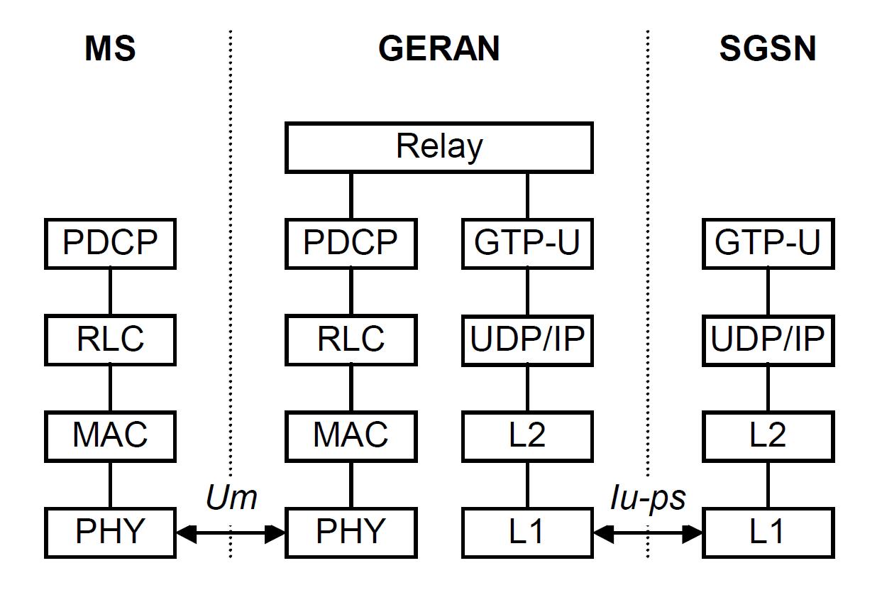
Besides all other interfaces that are common with GPRS, the EDGE specific interfaces are between the BSC/RNC and SGSN. Between these two network entites, both the GPRS Gb and the new Iu-ps interfaces are supported. The protocol stacks of the Iu-ps interface control plane and user plane are as below.

Iu-ps Control Plane Protocol Stacks


Iu-ps User Plane Protocol Stacks


4. EDGE Evolution

EDGE Evolution is an upgraded version of EDGE that completed standardization work in 2007 within Release 7 at 3GPP. EDGE Evolution is also referred to as EDGE II or Evolved EDGE by some industry sources. EDGE Evolution boosts the data speeds by up to 300 percent and significantly improves latency, coverage, and spectrum efficiency of existing GSM/EDGE equipment.

Compared to EDGE, EDGE Evolution is expected to provide:
• A dramatic increase in data rates. The actual amount depends on the version used, but EDGE Evolution is expected to quadruple the throughput rates for EDGE with peak theoretical network speeds of 1184 kbps to 1894 kbps in type 1 or type 2 respectively for the downlink and 473 to 947 kbps for the uplink.
• A 50 percent increase in spectral efficiency and capacity
• Reduced latency for initial access and round trip time, enabling better quality of service (QoS) for Push-to-Talk (PTT) and Voice over IP (VoIP)
• Compatibility with existing frequency plans, thus facilitating rapid deployment in existing networks
• A simple upgrade to existing GSM equipment allowing a more efficient use of scarce existing spectrum
• A better seamless experience for subscribers as they roam from HSPA networks to EDGE networks
• Compatibility with existing frequency plans, thus facilitating rapid deployment in existing networks

Thursday, July 15, 2010

Mobile Network Evolution: GPRS


GPRS (General Packet Radio Service) is a packet based upgrade to the GSM networks. It allows GSM networks to be truly compatible with the Internet. GPRS uses a packet-mode technique to transfer bursty traffic in an efficient manner. It promises data rates from 56 up to 114 Kbps and continuous connection to the Internet for mobile phone and computer users. Along the evolution path of the GSM network towards 3G and beyond, GPRS is refered as a 2.5G technology.

1. GPRS Network Architecture


2. GPRS Network Entities

2.1 MS
GPRS enabled MS.

2.2 BTS
Same as the GSM BTS.

2.3 BSC
The GSM BSC enhanced with the Packet Control Unit (PCU) to differentiates whether data is to be routed to the packet switched or circuit switched networks.

The PCU or Packet Control Unit is a hardware router that is added to the BSC. It differentiates data destined for the standard GSM network (circuit switched data) and data destined for the GPRS network (Packet Switched Data). The PCU itself may be a separate physical entity, or more often these days it is incorporated into the base station controller, BSC, thereby saving additional hardware costs.

2.4 SGSN
The SGSN or Serving GPRS Support Node element of the GPRS network provides a number of takes focussed on the IP elements of the overall system. It provides a variety of services to the mobiles:

• Packet routing and transfer
• Mobility management
• Attach/detach
• Logical link management
• Authentication
• Charging data

There is a location register within the SGSN and this stores location information (e.g., current cell, current VLR). It also stores the user profiles (e.g., IMSI, packet addresses used) for all the GPRS users registered with the particular SGSN.

2.5 GGSN
The GGSN, Gateway GPRS Support Node is one of the most important entities within the GPRS network architecture.

The GGSN organises the interworking between the GPRS network and external packet switched networks to which the mobiles may be connected. These may include both Internet and X.25 networks.

The GGSN can be considered to be a combination of a gateway, router and firewall as it hides the internal network to the outside. In operation, when the GGSN receives data addressed to a specific user, it checks if the user is active, then forwarding the data. In the opposite direction, packet data from the mobile is routed to the right destination network by the GGSN.

3. GPRS Interfaces and Protocols


4. GPRS Control and User Planes


5. GPRS Core Protocol -- GTP

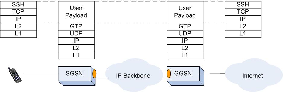
GPRS Tunnelling Protocol (GTP) is the core protocol used in GPRS network between the SGSN and the GGSN for GPRS service control and user data delivery. It is is a group of IP-based communications protocols. GTP can be classified into separate protocol subgroups according to their usage, GTP-C, GTP-U and GTP' respectively.

GTP-C is used within the GPRS core network for signaling between the GGSN and the SGSN. GTP-C includes the control procedures that allows the SGSN to activate a session on a user's behalf (PDP context activation), to deactivate the same session, to adjust quality of service parameters, or to update a session for a subscriber who has just arrived from another SGSN.

GTP-U is used for carrying user data within the GPRS Core Network and between the Radio Access Network and the core network. The user data transported can be packets in any of IPv4, IPv6, or PPP formats.

GTP' (GTP prime) uses the same message structure as GTP-C and GTP-U, but has an independent function. It can be used for carrying charging data from the Charging Data Function (CDF) to the Charging Gateway Function (CGF).


6. GPRS User Sessions -- PDP Context
A Packet Data Protocol (PDP) context is a GPRS user session established allowing the MS and the network to exchange IP packets with QoS specifications. A PDP Context has a record of parameters, which consists of all the required information for establishing the end-to-end connection:

• PDP Type
• PDP address type
• QoS profile request (QoS parameters requested by user)
• QoS profile negotiated (QoS parameters negotiated by network)
• Authentication type (PAP or CHAP)
• DNS type (Dynamic DNS or Static DNS)

Wednesday, July 14, 2010

Mobile Network Evolution: GSM -- The Starting Point


Global System for Mobile Communication (GSM) is a set of ETSI standards specifying the infrastructure for a digital cellular service. As a fully digital system, GSM allows both speech and data services and allows roaming across networks and countries. These features made GSM a very popular system, not only in european countries but also elsewhere in the world.

In the mobile network evolution path shown above, the GSM system is the starting point to be address in this series of articles.

1. GSM Network Architecture


2. GSM Network Entities

2.1 Mobile Station (MS)
The Mobile Station (MS) is the user equipment in GSM, i.e. the cellular phone itself. The MSs in GSM are independent from networks-providers. The identity of the subscriber is obtained from a SIM (Subscriber Identity Module) that has to be inserted into the MS to make it work. The SIM contains the IMSI (International Mobile Subscriber Identity) which uniquely identifies the subscriber to the network. It also contains information necessary to encrypt the connections on the radio interface. The MS itself is identified by an IMEI (International Mobile Equipment Identity), which can be obtained by the network upon request. Without the SIM, calls to and from the mobile station is not allowed, except that the alls to the international emergency number, 112, is allowed without the SIM.

2.2 Base Transciever Station (BTS)
The Base Transciever Station (BTS) is the entity corresponding to one cellular site communicating with the Mobile Stations. Usually, the BTS will have an antenna with several TRXs (radio transcievers) that each communicate on one radio frequency. Speech and data transmissions from the MS is encoded in the BTS from the special encoding used on the radio interface to the standard 64 kbit/s encoding used in telecommunication networks.

2.3 Base Station Controller (BSC)
A Base Station Controller (BSC) controls the magnitude of several hundred BTSs for subscriber registration, location update, call setup and handover control etc. It is the entrance point for an MS to gain access to the overall mobile network services.

2.4 Mobile Switching Centre (MSC)
The Mobile Switching Centre (MSC) is a typical telecom switch with extended functionalities to support mobile services. The basic function of the MSC is to switch speech and data connections between BSCs, with other MSCs or other GSM-networks and external non-mobile-networks. It also takes care of all mobility management tasks.

2.5 Visitors Location Register (VLR)
For each MSC, there is an associated VLR to store the information about all subscribers that are roaming within its service coverage. The subscriber infromation is obtained either through the MS initiated location update procedure when it enters the covered area or through the notification from the subscriber's Home Location Register (HLR). The VLR serves the routing of all service initiated or targeted to the MS.

2.6 Home Location Register (HLR)
The HLR is the home register of a subscriber. It is where the subscriber information, allowed services, authentication information, location information etc. of a subscriber are permanently stored.

2.7 Equipment Identity Register (EIR)
The Equipment Identity Register (EIR) is an optional register. Its purpose is to register IMEIs of mobile stations in use. By implementing the EIR the network provider can implement a widely range of control functions to the served MSs, such as blacklisting malfunctional or stolen mobile stations etc.

2.8 Gateway MSC (GMSC)
A Gateway Mobile Switching Centre (GMSC) provides the edge function within the mobile network. It terminates the PSTN (Public Switched Telephone Network) signalling and traffic formats and converts to protocols employed in mobile networks. For mobile terminated services, it interacts with the HLR (Home Location Register) to perform routing functions.

3. GSM Interfaces and Protocols


4. GSM Air Interface Channel Structure

Tuesday, July 13, 2010

Mobile Network Evolution: CDMAone to CDMA2000

Code Division Multiple Access (CDMA) is a method for transmitting simultaneous digital signals over a shared portion of the spectrum. As a competing technology to its European GSM peer and its successors, this American technology initiates an alternative cellular system implementation.

1. CDMAone

CDMAone refers to the original ITU IS-95 (CDMA) wireless interface protocol that was first standardized in 1993 and employed to build up the first CDMA cellular network. In the mobile network evolution term, CDMAone is considered as a second-generation (2G) mobile wireless technology.

There are two versions of IS-95, called IS-95A and IS-95B. The IS-95A protocol employs a 1.25-MHz carrier, operates in radio-frequency bands at either 800 MHz or 1.9 GHz, and supports data speeds of up to 14.4 Kbps. IS-95B can support data speeds of up to 115 kbps by bundling up to eight channels.


2. CDMA2000 Overview

CDMA2000 represents a family of standards which includes technologies as listed below. CDMA2000 is also known by its ITU name, IMT-2000 CDMA Multi-Carrier (MC).

i. CDMA 2000 1x
ii. CDMA 2000 1x EV DO
a) CDMA2000 1xEV-DO Release 0
b) CDMA2000 1xEV-DO Revision A (Rev A)
c) CDMA2000 1xEV-DO Revision B(Rev B)
d) CDMA2000 1xEV-DO Revision C(Rev C)
iii. CDMA 2000 1x EVDV
iv. CDMA 2000 3x

The CDMA 2000 standard was divided into two phases 1x and 3x. 1x is used to refer that the standard carrier on the air interface is 1.25 MHz, which is the same as for IS-95A/B. 3X is a multi-carrier approach, and is used to refer 3 times standard carrier of 1.25 MHz i.e. 3.75 MHz.

CDMA 2000 1x utilizes a single carrier of 1.25 MHz of radio spectrum as IS-95. However, it uses a different vocoder and walshcodes, 256/ 128 verses 64, allowing for higher data rates and more voice conversions than are possible over cdmaOne systems. 1x EV-DO means one carrier, which is data only, while 1x EV-DV means one carrier that supports data and voice services. However, when referring to CDMA 2000 3x, the use of 3.75 MHz of the spectrum, or 3x1.25 MHz, is defined with a change in the modulation scheme as well as the vocoders.

3. CDMA2000 1xRTT

CDMA2000 1xRTT is considered as a 2.5G (or 2.75G) technology. CDMA2000 1xRTT is the core CDMA2000 wireless air interface standard and is also known as 1x, 1xRTT, and IS-2000. The designation "1x", meaning "1 times Radio Transmission Technology", indicates the same RF bandwidth as IS-95 (CDMA-One): a duplex pair of 1.25 MHz radio channels. 1xRTT almost doubles the capacity of IS-95 by adding 64 more traffic channels to the forward link, orthogonal to the original set of 64. Although capable of higher data rates, most deployments are limited to a peak of 144 kbit/s. IS-2000 also made changes to the data link layer for the greater use of data services, including medium and link access control protocols and QoS.


4. CDMA2000 EV-DO

CDMA2000 EV-DO (Evolution-Data Optimized or Evolution-Data only) is refered as the CDMA version of 3G technology. It is a broadband access radio technology standardized by 3rd Generation Partnership Project 2 (3GPP2), provides access to mobile devices with air interface speeds of up to 2.4 Mbit/s with Rev. 0, up to 3.1 Mbit/s with Rev. A, upto 14.7 Mbit/s with Rev. B and upto 200 Mbit/s with Rev. C, etc.


CDMA2000 1xEV-DO requires a multi-mode device to be fully backward compatible with 1X and cdmaOne systems to support the all-IP network and the air interface that has been optimized for data.

CDMA2000 1xEV-DO Rev.0 provides a peak data rate of 2.4 Mbps in the forward link and 153 kbps in the reverse link in a 1.25 MHz CDMA carrier. With average throughput of 400-800 kbps in the forward link.

CDMA2000 1xEV-DO Rev A is an enhanced version of Rev.0,represents a major step in the evolution of CDMA2000 standards towards converged communication networks and ubiquitous delivery of voice and data services across fixed and wireless networks. The key features that the Rev.A provides are:
• High-speed data: Delivers a peak data rate of 1.8 Mbps on the reverse link and 3.1 Mbps on the forward link.
• Higher system capacity: Improves sector capacity within the 1.25 MHz channel. It has twice the sector capacity on the down link and is 1.2 times higher on the forward link compared to Release 0.
• Improved Quality of Service (QoS): Lower latency, prioritization of low-latency applications and QoS software enhancements added to Revision A improve performance of delay-sensitive applications such as VoIP, push-to-talk, instant messaging and video telephony.
• VoIP: Is possible because of the high data rate on the reverse link, lower latency and improved QoS.

CDMA 2000 1x Ev-DO Rev-B introduces a 64-QAM modulation scheme and will deliver peak rates of 73.5 Mbps in the forward link and 27 Mbps in the reverse link through the aggregation of 15, 1.25 MHz carriers within 20 MHz of bandwidth. A single 1.25 MHz carrier and an aggregated 5 MHz carrier in the forward link will deliver a peak rate of up to 4.9 Mbps and 14.7 Mbps, respectively.

CDMA 2000 1x Ev-DO Rev-C delivers higher data rates and spectral efficiency along with low latency, making it ideal for enriched multimedia services. Revision C supports flexible and dynamic channel bandwidth scalability from 1.25 MHz up to 20 MHz and are backward-compatible with Revisions A and B. Revision C not only increases the peak rates up to 200 Mbps in the downlink but also provides significant gain in sector throughput.

5. CDMA2000 EV-DV

CDMA2000 EV-DV supports up to 3.1 Mbps forward link throughput. One of the advantageous of EV-DV is its ability to give carriers both voice and broadband data on a single channel, using the same legacy digital voice technology operating over current 1x networks.

EV-DV has been commercially unsuccessful due to lack of carrier interest.


6. CDMA2000 3x

CDMA2000 3x is an ITU-approved third-generation (3G) mobile wireless technology. It is also known as Multi-Carrier or MC.

CDMA2000 3x utilizes a pair of 3.75-MHz radio channels (i.e., 3 X 1.25 MHz) to achieve higher data rates. The 3x version of CDMA2000 has not been deployed and is not under development at present.

Monday, July 12, 2010

CDMA2000 Protocols

1. Overview

CDMA2000, also known as IMT-CDMA Multi-Carrier or IS-2000 is a technology for CDMA operators to advance their cdmaOne/IS-95 to 2.5G and 3G cellular networks. 3GPP2, the standard body behind CDMA2000, defines all the network functionalities, interfaces and operation protocols.

As adopted by a lot of operators, CDMA2000 is normally deployed in several phases. The first phase, CDMA2000 1x, supports an average of 144 kbps packet data in a mobile environment. The second release of 1x, called 1x-EV-DO supports data rates up to 2 Mbits/sec on a dedicated data carrier. Finally, 1x-EV-DV will support even higher peak rates, simultaneous voice and high-speed data, as well as improved Quality of Service mechanisms.

Major CDMA2000 network elements and interfaces are shown in the following figure.


A summary of all CDMA2000 protocols are listed as follows:

- A1: A1 Signaling, SCCP, MTP3, MTP2, MTP1
- A3: A3 Signaling, TCP, IP, AAL5, SSSAR, AAL2
- A7: A7 Signaling, TCP, IP, AAL5
- A8: GRE, IP, PPP
- A9: A9 signaling TCP, UDP, IP
- A10: GRE, IP, PPP
- A11: A11 signaling, UDP, IP, PPP, Mobile IP
- A12: RADIUS, UDP, IP, PPP
- A13: A13 Signaling, TCP/UDP, IP
- A14: A14 Signaling, TCP/UDP, IP
- A15: A15 Signaling, TCP/UDP, IP
- 3GPP2 IOS 3.x and IOS 4.x
- Other Protocols: PPP in HDLC-likeFraming, IPCP, Diameter, IKE


2. A1 Interface

The A1 interface carries signaling information between the Call Control (CC) and Mobility Management (MM) functions of the MSC and the call control component of the BS (BSC). The application signaling protocol used over this interface is the Base Station Application Part (BSAP). BSAP includes two sub-application parts; the BS management application part (BSMAP), and the direct transfer application part (DTAP).

The BS Management Application Part (BSMAP) supports all Radio Resource Management and Facility Management procedures between the MSC and the BS, or to a cell(s) within the BS. BSMAP messages are not passed to the MS, but are used only to perform functions at the MSC or the BS. A BSMAP message (Complete Layer 3 Information) is also used together with a DTAP message to establish a connection for a MS between the BS and the MSC, in response to the first layer 3 air interface message sent by the MS to the BS for each MS system request.

The Direct Transfer Application Part (DTAP) messages are used to transfer call processing and mobility management messages between the MSC and BS. DTAP messages carry information that is primarily used by the MS. The BS maps the DTAP messages going to and coming from the MSC from/into the appropriate air interface signaling protocol.

BSMAP Messages

- Additional Service Notification
- ADDS Page
- ADDS Page Ack
- ADDS Transfer
- ADDS Transfer Ack
- Assignment Complete
- Assignment Failure
- Assignment Request
- Authentication Request
- Authentication Response
- Base Station Challenge
- Base Station Challenge Response
- Block
- Block Acknowledge
- BS Service Request
- BS Service Response
- Clear Command
- Clear Complete
- Clear Request
- Complete Layer 3 Information
- Feature Notification
- Feature Notification Ack
- Handoff Command
- Handoff Commenced
- Handoff Complete
- Handoff Failure
- Handoff Performed
- Handoff Request
- Handoff Request Acknowledge
- Handoff Required
- Handoff Required Reject
- PACA Command
- PACA Command Ack
- PACA Update
- PACA Update Ack
- Paging Request
- Privacy Mode Command
- Privacy Mode Complete
- Radio Measurements for Position Request
- Radio Measurements for Position Response
- Rejection
- Rejection
- Reset Acknowledge
- Reset Circuit
- Reset Circuit Acknowledge
- SSD Update Request
- SSD Update Response
- Status Request
- Status Response
- Transcoder Control Acknowledge
- Transcoder Control Request
- Unblock
- Unblock Acknowledge
- User Zone Reject

DTAP Messages

- Additional Service Request
- ADDS Deliver
- ADDS Deliver Ack
- Alert With Information
- Authentication Request
- Authentication Response
- Base Station Challenge
- Base Station Challenge Response
- CM Service Request
- Connect
- Flash with Information
- Flash with Information Ack
- Location Updating Accept
- Location Updating Reject
- Location Updating Request
- Paging Response
- Parameter Update Confirm
- Parameter Update Request
- Rejection
- Service Release
- Service Release Complete
- SSD Update Request
- SSD Update Response
- Status Request
- Status Response
- User Zone Reject
- User Zone Update
- User Zone Update Request

3. A2 Interface

The A2 interface carries 64/56 kbps PCM information (voice/data) or 64 kbps Unrestricted Digital Information (UDI, for ISDN) between the Switch component of the MSC and one of the following:
- the channel element component of the BS (in the case of an analog air interface), or
- the Selection/Distribution Unit (SDU) function (in the case of a voice call over a digital air interface),

4. A3 Interface

The A3 interface carries coded user information (voice/data) and signaling information between the SDU function and the channel element component of the BS (BTS). This interface is composed of signaling and user traffic sub-channels between two BSCs. It provides the ability to establish and remove A3 traffic connections.

A3 signaling messages are listed as follows:

- A3-Connect
- A3-Connect Ack
- A3-Remove
- A3-Remove Ack
- A3-Drop
- A3-Propagation Delay Measurement Report
- A3-IS-95 FCH Forward
- A3-IS-95 FCH Reverse
- A3-Physical Transition Directive
- A3-Physical Transition Directive Ack
- A3-IS-2000 FCH Forward
- A3-IS-2000 FCH Reverse
- A3-Traffic Channel Status
- A3-IS-2000 DCCH Forward
- A3-IS-2000 DCCH Reverse
- A3-IS 2000 SCH Forward
- A3-IS 2000 SCH Reverese
- A3-FCH Forward Traffic Frame
- A3-DCCH Forward Traffic Frame
- A3-FCH Reverse Traffic Frame
- A3-DCCH Reverse Traffic Frame
- A3-SCH Reverse Traffic Frame

5. A5 Interface

The A5 interface carries a full duplex stream of bytes between the MSC and the SDU function.

6. A7 Interface

The A7 interface provides direct BS to BS signaling for the support of an efficient soft handoff procedure.

A7 signaling messages are:

- A7-Handoff Request
- A7-Handoff Request Ack
- A7-Drop Target
- A7-Drop Target Ack
- A7-Target Removal Request
- A7-Target Removal Response
- A7-Source Transfer Performed
- A7-Reset
- A7-Reset Acknowledge
- A7-Paging Channel Message Transfer
- A7-Paging Channel Message Transfer Ack
- A7-Access Channel Message Transfer
- A7-Access Channel Message Transfer Ack
- A7-Burst Request
- A7-Burst Response
- A7-Burst Commit
- A7-Burst Release

7. A8 Interface

The A8 interface carries user traffic between the BS and the PCF. The A8 interface uses the Generic Routing Encapsulation (GRE) protocol to provide a mechanism for encapsulating arbitrary packets within an arbitrary transport protocol for traffic delivery between BSC and PCF.

8. A9 Interface

The A9 interface carries signaling information between the BS and the PCF. The A8/A9 interfaces support mobility between BSCs under the same PCF.

The A9 interface signaling messages are listed below:

- A9-Setup A8
- A9-Connect A8
- A9-Disconnect A8
- A9-Release A8
- A9-Release A8 Complete
- A9-BS Service Request
- A9-BS Service Response
- A9-AL Connected
- A9-AL Connected Ack
- A9-AL Disconnected
- A9-AL Disconnected Ack
- A9-Short Data Delivery
- A9-Short Data Ack
- A9-Update-A8
- A9-Update-A8-Ack
- A9-Version Info
- A9-Version Info Ack

9. A10 Interface

The A10 interface carries user traffic between the PCF and the PDSN. The A10 interface uses the Generic Routing Encapsulation (GRE) protocol to provide a mechanism for encapsulating arbitrary packets within an arbitrary transport protocol for traffic delivery between PCF and PDSN.


10. A11 Interface

The A11 interface carries signaling information between the PCF and the PDSN for packet data services and provides a signaling connection between a PCF and PDSN pair (A11). A11 signaling messages are also used for passing accounting related and other information from the PCF to the PDSN. The A10/A11 interfaces support mobility between PCFs under the same PDSN.

The A11 signaling messages are

- Registration Request
- Registration Reply
- Registration Update
- Registration Acknowledgment

11. A12 Interface

The A12 interface uses RADIUS protocol for authentication purposes.

12. A13 Interface

The A13 protocol is responsible for information exchange between the source and target AN. The protocol is divided up into information from the target to source direction, and information from the source to the target direction. Signaling over the A13 interface requires a reliable transport protocol and appropriate addressing and routing mechanisms to deliver messages from the target to source destination.

All A13 messages are listed below

- A13-Session Information Request
- A13-Session Information Confirm
- A13-Session Information Reject
- A13-Session Information Response

13. A14 Interface

The A14 interface between the AN and the SC/MM function of the PCF is used for performing HRPD Session and HRPD mobility related operations. Procedures included in A14 interface functions are

• UATI assignment procedure.
• General updating procedure.
• Terminal authentication.
• Session release.
• Session information updating procedure.
• Paging procedure.

For supporting above procedures, the A14 interfaces uses the following messages:

- General Update
- General Update Complete
- Authentication Command
- Authentication Request
- Authentication Response
- Authentication Completed
- Authentication Completed Ack
- UATI Request
- UATI Assignment
- UATI Complete
- UATI Complete Ack
- UATI Assignment Failure
- Session Release
- Session Release Complete
- Paging Request
- Paging Request Ack
- Paging Response
- Paging Response Ack
- Session Information Update
- Session Information Update Ack
- Session Release Command
- Authentication Failure
- Authentication Failure Ack
- Keep Alive Request
- Keep Alive Request Ack

14. A15 Interface

The A15 interface is used for sending paging request messages from the AN that manages the registered sector to the ANs that send paging messages over the air. This interface is used for inter AN paging.

All messages used in A15 signaling are as follows:

- Paging Request
- Paging Response
- Paging Response Ack

Thursday, April 29, 2010

IP/PSTN Convergence in NGN

A marketing presentation on the IP/PSTN convergence towards the Next Generation Network (NGN) in Chinese presented in 2005 Beijing NGN Summit. Click the following link to view....

2005 Bejing NGN summit presentation

GR303 Architecture

An MGCP/MEGACO based GR303 architecture... click the following link to view details

GR303 Architecture

TRIP and TGREP in Distributed Network Routing Architecture

TRIP and TGREP applications in distributed network routing architecture, click the following link to view ...

TRIP and TGREP in Distributed Network Routing Architecture

Traffic Engineering and Dynamic Routing

Slides shows the traffic engineering and dynamic routing applications in a packet based telephony network... click the following link for details

Traffic Engineering and Dynamic Routing

Friday, May 9, 2008

UMTS network domains

W-CDMA based 3G mobile network technology, Universal Mobile Telecommunications System (UMTS) integrates traditional GSM voice services and newly emerged data services into a universal integrated network infrastructure. Serving different network functions, such an infrastructure

GERAN stands for GSM EDGE Radio Access Network. It is the term given to the second-generation digital cellular GSM radio access technology, including its evolutions in the form of EDGE (Enhanced Data rates for Global Evolution) and, for most purposes, the General Packet Radio Service (GPRS). GERAN enabled 3G service continuity over the GSM infrastructure by improving speed, latency and mobility experience for data applications. It also introduced a lot more new applications and improved the network efficiency. GERAN includes BTSs and BSCs.

UTRAN, short for UMTS Terrestrial Radio Access Network, is the new generation radio access network within the UMTS architecture. Samilar to GERAN, UTRAN contains the base stations, which are called Node Bs, and Radio Network Controllers (RNC). The RNC provides control functionalities for one or more Node Bs.

UMTS CN (core network) includes network elements within
  • legacy GSM: MSC, VLR, HLR, EIR etc.
  • GPRS/EDGE: SGSN, GGSN etc.
  • IMS core: CBC, CSCF, MRCF, MGCF, SLF, HSS, AS etc.

The following figure shows a brief of the UMTS domains.


Thursday, May 8, 2008

Mobile Network Evolution: GSM to UMTS

1. GSM: the 2G mobile network

Global System for Mobile communications (GSM) is the most popular standard for mobile communications in the world. Its network architecture is shown in figure 1.


Figure 1. GSM network architecture

2. GPRS: the 2.5G mobile network
General Packet Radio Servcie (GPRS) is a packet oriented mobile data service developed on the GSM infrastructure. It provides data transfer rate from 56 to 114 kbits.s. GPRS network architecture is as shown in figure 2.


Figure 2. GPRS network architecture

3. EDGE (EGPRS): the 2.75G mobile network

Enhanced data rates for GSM evolution (EDGE), enhanced GPRS (EGPRS) or IMT Signle Carrier (IMT-SC) is a packet mobile technology evolved from the GPRS infrastructure providing enhanced data transfer rate and reliability.

The network architecture for EDGE is basically the same as that for GPRS, the same network elements, the same interfaces, the same protocols and the same procedures. The only minor differences lie in the air interface improvement for supporting higher data transfer rate and reliability.

4. UMTS: the 3G mobile network

Universial Mobile Telecommunications System (UMTS) is the 3G mobile network technology evolved from the GSM-GPRS based network architecture. The overall UMTS evolution experienced different stages (also widely called stages).

4.1 Relsease 99

  • 64kbits/s circuit switched bearer services
  • 384 kbits/s packet switched bearer services
  • location services
  • call services


4.2 Release 4

  • EDGE radio
  • multimedia messaging
  • MExE (mobile execution environment)
  • improved locationed services
  • IP multimedia services (IMS)


4.3 Release 5

  • IP multimedia subsystem (IMS)
  • IPv6, IP transport in UTRAN
  • improvements in GERAN, MExE etc,
  • HSDPA


4.4 Release 6

  • WLAN integration
  • multimedia broadcast and multicast
  • improvements in IMS
  • HSUPA


4.5 Release 7

  • Fix mobile convergence
  • DSL access

Tuesday, May 6, 2008

SS7 Mobile Application Part (MAP)

SS7 Mobile Application Part (MAP) is the core protocol used in the mobile core. In summary, what MAP does are:


  • handles all non-call related signaling between different mobile network elements, such as registration, authentication, subscriber profile update/query, romaing and mobility management, supplementary service control, operation and maintenance and short message control etc.
  • it is designed to govern the interactions between any two of the the following mobile core network elements: MSC, VLR/HLR, AUC, GMSC, EIR, SMS etc.
  • it is a query - response type of protocol
  • it contains a number of application system elements (ASE)
  • Functionally, MAP can be devided into mobile management (MM) and basic service control functionality categories

A list of mobile core network elements using MAP for signaling are

  • EIR Equipment Identity Register - usually integrated with HLR
  • GCR Group Call Register
  • GGSN Gateway GPRS Support Node - for interfacing to IP or other PD networks
  • GMLC Gateway Mobile Location Center - for interfacing to Location Services
  • GMSC Gateway MSC - for routing calls from visited network
  • gsmSCF GSM Service Control Function - IN service control element
  • HLR Home Location Register - the key database
  • MSC Mobile services Switching Center
  • NPLR Number Portability Location Center - for locating an HLR
  • SGSN Serving GPRS Support Node - the "MSC/VLR" for PS services
  • SIWFS Shared Interworking Function Server - for interfacing CS data services to IP orother PD networks
  • SMS GWMSC SMS Gateway MSC - for terminating SMS routing
  • SMS IWMSC SMS Interworking MSC - for originating SMS routing
  • USSDC USSD Center - part of gsmSCF
  • VBS/VGCS Anchor MSC Voice broadcast/group call service Anchor MSC - specified/not implemented
  • VBS/VGCS Relay MSC Voice broadcast/group call service relay MSC - specified/not implemented
  • VLR Visitor Location Register -in practice integrated with MSC
  • VMSC Visited MSC

Accordingly, the core MAP interfaces between any two of the associated network elements are shown in the following figure.


Over all above interfaces, MAP applications accomplish the designated functionalities through the common MAP services listed below:


  • MAP-OPEN/MAP-CLOSE services: For establishing and clearingMAP dialogues between peer-MAP service users
  • MAP-DELIMETER service: For accessing to functions below the application layer
  • MAP-U-ABORT/MAP-P-ABORT services: For reporting abnormal situations
  • MAP-NOTICE service: Notification from the provider, not affecting state of the dialogue

MAP services provided to the MAP applications are of the following categories

1. Location management services

  • MAP_UPDATE_LOCATION
  • MAP_CANCEL_LOCATION
  • MAP_SEND_IDENTIFICATION
  • MAP_PURGE_MS
  • MAP_UPDATE_GPRS_LOCATION
  • MAP-NOTE-MM-EVENT

2. Page and search services

  • MAP_PAGE
  • MAP_SEARCH_FOR_MS

3. Access management services

  • MAP_PROCESS_ACCESS_REQUEST

4. Handover services

  • MAP_PREPARE_HANDOVER
  • MAP_SEND_END_SIGNAL
  • MAP_PROCESS_ACCESS_SIGNALLING
  • MAP_FORWARD_ACCESS_SIGNALLING
  • MAP_PREPARE_SUBSEQUENT_HANDOVER
  • MAP_ALLOCATE_HANDOVER_NUMBER
  • MAP_SEND_HANDOVER_REPORT

5. Authentication management services

  • MAP_AUTHENTICATE
  • MAP_SEND_AUTHENTICATION_INFO
  • MAP_AUTHENTICATION_FAILURE_REPORT

6. Security management services

  • MAP_SET_CIPHERING_MODE

7. International mobile equipment identities management services

  • MAP_CHECK_IMEI
  • MAP_OBTAIN_IMEI

8. Subscriber management services

  • MAP-INSERT-SUBSCRIBER-DATA
  • MAP-DELETE-SUBSCRIBER-DATA

9. Identity management services

  • MAP-PROVIDE-IMSI
  • MAP-FORWARD-NEW-TMSI

10. Fault recovery services

  • MAP_RESET
  • MAP_FORWARD_CHECK_SS_INDICATION
  • MAP_RESTORE_DATA

11. Subscriber Information services

  • MAP-ANY-TIME-INTERROGATION
  • MAP-PROVIDE-SUBSCRIBER-INFO
  • MAP-ANY-TIME-SUBSCRIPTION-INTERROGATION
  • MAP-ANY-TIME-MODIFICATION
  • MAP-NOTE-SUBSCRIBER-DATA-MODIFIED

12. Operation and maintenance services -- Subscriber tracing services

  • MAP-ACTIVATE-TRACE-MODE
  • MAP-DEACTIVATE-TRACE-MODE
  • MAP-TRACE-SUBSCRIBER-ACTIVITY

13. Other operation and maintenance services

  • MAP-SEND-IMSI

14. Call handling services

  • MAP_SEND_ROUTING_INFORMATION
  • MAP_PROVIDE_ROAMING_NUMBER
  • MAP_RESUME_CALL_HANDLING
  • MAP_PREPARE_GROUP_CALL
  • MAP_PROCESS_GROUP_CALL_SIGNALLING
  • MAP_FORWARD_GROUP_CALL_SIGNALLING
  • MAP_SEND_GROUP_CALL_END_SIGNAL
  • MAP_SEND_GROUP_CALL_INFO
  • MAP_SET_REPORTING_STATE
  • MAP_STATUS_REPORT
  • MAP_REMOTE_USER_FREE
  • MAP_IST_ALERT
  • MAP_IST_COMMAND
  • MAP_RELEASE_RESOURCES

15. Supplementary services related services

  • MAP_REGISTER_SS
  • MAP_ERASE_SS
  • MAP_ACTIVATE_SS
  • MAP_DEACTIVATE_SS
  • MAP_INTERROGATE_SS
  • MAP_REGISTER_PASSWORD
  • MAP_GET_PASSWORD
  • MAP_PROCESS_UNSTRUCTURED_SS_REQUEST
  • MAP_UNSTRUCTURED_SS_REQUEST
  • MAP_UNSTRUCTURED_SS_NOTIFY
  • MAP_SS_INVOCATION_NOTIFY
  • MAP_REGISTER_CC_ENTRY
  • MAP_ERASE_CC_ENTRY

16. Short message service management services

  • MAP-SEND-ROUTING-INFO-FOR-SM
  • MAP-MO-FORWARD-SHORT-MESSAGE
  • MAP-REPORT-SM-DELIVERY-STATUS
  • MAP-READY-FOR-SM
  • MAP-ALERT-SERVICE-CENTRE
  • MAP-INFORM-SERVICE-CENTRE
  • MAP-SEND-INFO-FOR-MT-SMS
  • MAP-SEND-INFO-FOR-MO-SMS
  • MAP-MT-FORWARD-SHORT-MESSAGE
  • MAP-MT-FORWARD-SM-FOR-VGCS

17. Network-Requested PDP Context Activation services

  • MAP_SEND_ROUTING_INFO_FOR_GPRS
  • MAP_FAILURE_REPORT
  • MAP_NOTE_MS_PRESENT_FOR_GPRS

18. Location Service Management Services

  • MAP-SEND-ROUTING-INFO-FOR-LCS
  • MAP-PROVIDE-SUBSCRIBER-LOCATION
  • MAP-SUBSCRIBER-LOCATION-REPORT

MAP message addressing scheme is shown in the following figure.

Monday, May 5, 2008

Mobile Network A Interface

The interface between a BSC (Base Station Controller) and an MSC (Mobile Switching Center) is called the A interface. Running on the standard connection of 64Kbits/s or 2048 Kbits/s (or 1544 Kbits/s in North America), SS7 MTP and SCCP transporation protocols are used to deliver the Base Station Application Part (BSSAP) between the BSC and MSC.

Base Station Application Part (BSSAP) can further be devided into

  1. Direct Transfer Application Part (DTAP)
  2. Base Station System Operation and Management Part (BSSOMAP)

The DTAP is used to transfer call control and mobility management messages between the MSC and MS. The DTAP information in these messages is not interrepted by the BSC. The majority of radio interface messages are transferred across the A interface by DTAP, except for messages belonging to the Radio Resource (RR) management protocol.

The DTAP message header is as shown in the following figure.


The protocol discriminator distinguishes the payload protocol of the messages as follows:

  • 0000 Group call control
  • 0001 Broadcast call control
  • 0010 PDSS1
  • 0011 Call control, call relate SS messages
  • 0100 PDSS2
  • 0101 Mobility Management messages
  • 0110 Radio resource meanagement messages
  • 1001 SMS messages
  • 1011 Non-call related SS messages
  • 1110 Extension of the PD to one octet length
  • 1111 Tests procedures

The message type field defines the different messages in different protocols.

The BSSOMAP is used to convey the base station operation and management messages.


Saturday, May 3, 2008

Mobile Network Abis Interface

The interface between the BSC (base station controller) and BTS (base transceiver station) is called A bis responsible for the following functions between a BSC and a BTS:
  1. Voice-data traffic exchange

  2. Signaling exchange between the BSC and the BTS

  3. Transporting synchronization information from the BSC to the BTS
Physically, an A bis interface is a primiary rate connection of 64Kbits/s or 2048Mbits/s (or 1.5Mbits/s in North America) digital link. On these digital links, bearer of signaling traffic channels of 16 or 64 Kbits/s are established.


The data link layer (layer 2) protocol running over the A bis interface is LAPD. Running on top of the LAPD is the layer 3 BTS management (BTSM) protocol, which include 3 major functions:
  1. Traffic management (radio resource control and connection control) function over the Radio Signaling Link (RSL) (SAPI=0)

  2. Operation and maintenance function over the operation and maintenance link (OML) (SAPI=62)

  3. Layer 2 management message function over the layer 2 management link (L2ML) (SAPI=63)


Amongst these 3 functions, traffic management function is the most important one. In details, this functional block includes

  1. Radio link layer management procedures controlling the establish, modify and release of LAPDm connections over the air interface (Um)

  2. Dedicated channel management procedures controlling the ciphering, channel measurement transportation, transmitter power control, handover detection and dedicated channel modification etc.

  3. Common channel management procedures for transferring channel requests from MSs, paging MSs, CCCH traffic load measurements, BCCH broadcast information modification, channel assignment and cell broadcast short message transmission etc.

  4. TRX management procedures for free traffic channel measurements or flow control.
Over all, A bis layer 3 procedures are
  1. RLM Radio Link Layer Management.

  2. DCM Dedicated Channel Management.

  3. CCM Common Channel Management.

  4. TRX Transceiver Management.

  5. O&M Operating and Maintenance.


Radio Link layer Management messages includes

  1. (01) DATA-REQ: Data request.

  2. (02) DATA-IND: Data indication.

  3. (03) ERROR-IND: Error indication.

  4. (04) IS-REQ: Establish request.

  5. (05) IS-CONF: Establish confirm.

  6. (06) IS-IND: Establish indication.

  7. (07) REL-REQ: Release request.

  8. (08) REL-CONF: Release confirm.

  9. (09) REL-IND: Release indication.

  10. (0a) UNIT-DT-REQ: Unit data request.

  11. (0b) UNIT-DT-IND: Unit data indication.

Dedicated Channel Management messages

  1. (30) BS-POWER-CTRL: Base Station power control.

  2. (21) CHAN-ACT: Channel activation.

  3. (22) CHAN-ACT-ACK: Channel activation acknowledge.

  4. (23) CHAN-ACT-NACK: Channel activation negative acknowledge.

  5. (24) CONN-FAILURE: Connection failure.

  6. (25) DEACTIV-SACCH: Deactivate SACCH.

  7. (26) ENCRYPT-COMM: Encryption command.

  8. (27) HANDOVER-DET: Handover detection.

  9. (28) MEASURE-RES: Measurement result.

  10. (2a) MODE-MOD-ACK: Mode modify acknowledge.

  11. (2b) MODE-MOD-NACK: Mode modify negative acknowledge.

  12. (29) MODE-MOD-REQ: Mode modify request.

  13. (2f) MS-POWER-CTRL: Mobile System power control.

  14. (2d) PHYS-CON-CONF: Physical context confirm.

  15. (2c) PHYS-CON-REQ: Physical context request.

  16. (32) PREP-MEAS-RES: Preprocessed measurement result.

  17. (31) PREPROC-CONF: Pre-processing configuration.

  18. (33) RF-CH-REL-ACK: RF channels release acknowledge.

  19. (2e) RF-CHANN-REL: Radio Frequency channel release.

Common Channel Management messages

  1. (11) BCCH-INFO: BCCH information.

  2. (12) CCCH-LOAD-IND: CCCH load indication.

  3. (13) CHANNEL-RQD: Channel required.

  4. (14) DELETE-IND: Delete indication.

  5. (16) IMM-ASS-COM: Immediate assign command.

  6. (15) PAGING-CMD: Paging command.

  7. (17) SMS-BC-REQ: SMS broadcast request.

TRX Management messages

  1. (19) RF-RES-IND: Radio frequency resource indication.

  2. (1A) SACCH-FILL: SACCH filling.

  3. (1B) OVERLOAD: Overload.

  4. (1C) ERR-REP: Error report.

Operating & Maintenance messages

  1. (80) O&M Message: Operation and maintenance messages.

  2. (40) MMI Transfer: Man/machine interface transfer.

  3. (20) TRAU O&M: Transcoder/transfer rate adapter unit.

Friday, May 2, 2008

Mobile Network Air Interface – logical channels and protocols

Mobile network air interface is the interface between mobile stations (MSs) and the Base Transceiver Stations (BTSs). The fundamentals of this interface are a set of protocols running over a set of logical channels.

1. Logical channels

Air interface layer 1 defines a series of logical channels which are made available in either an unassigned random access mode to all users or a dedicated mode assigned to a specific user.
In general, the logical channels are of two major categories, the traffic channels (TCHs) and the signaling channels respectively.

Traffic channels (TCHs) are for user payload data only. Using an ISDN term, they are called the mobile B channels (Bms). Bms can be used in half rate and are then called the lower rate mobile channels (Lms). TCHs possess the following characteristics in terms of functionalities and usages.

a) no Layer 3 control information is carried
b) can be used in either a circuit based mode or a packet based mode,
c) in the circuit based mode, they provide transparent data connection or a specially treated connection according to the carried service
d) in the packet based mode, the carry the OSI layer 2/3 user data (X.25 or other protocols)
e) a TCH can be used as a full-rate Bm or split into two half-rate Lms used by different subscribers
f) one Bm capacity: 13 kbits/s digital voice or 12/6/3.6 kbits/s data stream
g) one Lm capacity: half-rate digital voice or 6/3.6 kbits/s data stream

Signaling channels are for passing signaling and control messages, similar to the ISDN D channel, they are also called the mobile D channels (Dms).

A Dm can be one of the following types

a) Broadcast channel (BCH): a BSS to MS unidirectional broadcast channel, can be further divided into:
a.1) Broadcast control channel (BCCH): carries information about the radio network: radio channel configuration, synchronization information, registration identifier, structural organization of CCCH
a.2) Frequency correction channel (FCCH): layer 1 only,
a.3) Synchronization channel (SCH): broadcast information to identify a BTS, data and frame synchronization. Layer 1 only.

b) Common control channel (CCCH): a BSS to MS unidirectional broadcast channel, deal with access management functions: dedicated channel assignment, MS paging etc. CCCH includes
b.1) Random access channel (RACH): uplink portion of CCCH, slotted Aloha, for MS to ask for a dedicated signaling channel (SDCCH)
b.2) Access grant channel (AGCH): the downlink portion of CCCH, used to assign an SDCCH or a TCH to an MS.
b.3) Paging channel (PCH): part of the downlink of the CCCH, used to page the MS.

c) Dedicated/Associate Control channel (DCCH/ACCH):
c.1) DCCH: bidirectional point-to-point signaling channel
c.1.1) Standalone dedicated control channel (SDCCH): for location update or connection setup etc.
c.2) ACCH: dedicated control channel assigned in connection with a TCH or a standalone dedicated control channel (SDCCH)
c.2.1) Slow associated control channel (SACCH): assigned and used with a TCH or an SDCCH, carries information for optimal radio operation, e.g. synchronization commands, Tx power control, report on channel measurements etc.
c.2.2) Fast associated control channel (FACCH): portion of TCH used for signaling.

d) Cell broadcast channel (CBCH) : broadcast short messages, share the same physical channel with SDCCH.

Figure 1 shows the logical channel classification.


Figure 1 GSM air interface logical channels


2. Protocols

Protocols running over the air interface are mainly for the following purposes:
a) Mobile LAPD (LAPDm), the data link protocol running over the layer 1.
b) Radio resource control (RR), deals with the allocation, de-allocation, and parameter control of the radio channel. RR is running in between of MS and BTS or MS and BSC.
c) Mobility management (MM), deals with location administration and handoff control.
d) Circuit mode connection/call management (CM), manages the setup and termination of calls.

Figure 2 shows the air link protocols and layering.


Figure 2 GSM air interface protocols and layering

Figure 3 shows the incoming call protocol interactions over the logical channels.


Figure 3 Protocol interactions over the air interface logical channels (incoming call case)